Modbus Server
The modbus_server component creates a RS485 connection to let your ESPHome node act as a Modbus server, allowing a ModBUS client to read data (like sensor values) from your ESPHome node.
You must set the role attribute of the Modbus Component to server.

Hardware setup

You need an RS485 transceiver module:
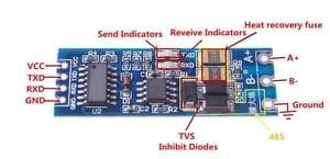
See How is this RS485 module working? on stackexchange for more details.
The transceiver connects to the UART of the MCU. For ESP32, pin 16 to TXD and pin 17 to RXD are the default ones but any other pins can be used as well. 3.3V to VCC and naturally GND to GND.
On the bus side, you need 120 Ohm termination resistors at the ends of the bus cable as per Modbus standard. Some transceivers have this already soldered onboard, while some slave devices may have them available via a jumper or a DIP switch.
ℹ️ Note
If you are using an ESP8266, serial logging may cause problems reading from UART. For best results, hardware serial is recommended. Software serial may not be able to read all received data if other components spend a lot of time in the
loop().For hardware serial only a limited set of pins can be used. Either
tx_pin: GPIO1andrx_pin: GPIO3ortx_pin: GPIO15andrx_pin: GPIO13.The disadvantage of using the hardware UART is that you can’t use serial logging because the serial logs would be sent to the Modbus device(s) instead, causing errors.
Serial logging can be disabled by setting
baud_rate: 0.See Logger Component for more details
logger:
    level: <level>
    baud_rate: 0
Configuration variables
modbus_id (Optional, ID): Manually specify the ID of the
modbushub.address (Required): The Modbus address of the server device.
server_courtesy_response (Optional): Configuration block to enable the courtesy response feature when the device is acting as a Modbus server.
- enabled (Optional, boolean): Whether to enable the courtesy response feature.
Defaults to
false. - register_last_address (Optional, integer): The highest Modbus register address (inclusive) up to which undefined registers are allowed to be read and will be padded with a default value.
Any read request that includes undefined registers within this range will return the value specified by
register_valueinstead of triggering an exception. Defaults to65535 - register_value (Optional, integer): The 16-bit value (range: 0–65535) to return for undefined registers within the address range defined by
register_last_address. Defaults to0.
- enabled (Optional, boolean): Whether to enable the courtesy response feature.
Defaults to
server_registers (Optional): A list of registers that are responded to when acting as a server.
address (Required, integer): start address of the first register in a range
value_type (Optional): datatype of the mod_bus register data. The default data type for ModBUS is a 16 bit integer in big endian format (network byte order, MSB first)
U_WORD: unsigned 16 bit integer, 1 register,uint16_tS_WORD: signed 16 bit integer, 1 register,int16_tU_DWORD: unsigned 32 bit integer, 2 registers,uint32_tS_DWORD: signed 32 bit integer, 2 registers,int32_tU_DWORD_R: little endian unsigned 32 bit integer, 2 registers,uint32_tS_DWORD_R: little endian signed 32 bit integer, 2 registers,int32_tU_QWORD: unsigned 64 bit integer, 4 registers,uint64_tS_QWORD: signed 64 bit integer, 4 registersint64_tU_QWORD_R: little endian unsigned 64 bit integer, 4 registers,uint64_tS_QWORD_R: little endian signed 64 bit integer, 4 registers,int64_tFP32: 32 bit IEEE 754 floating point, 2 registers,floatFP32_R: little endian 32 bit IEEE 754 floating point, 2 registers,float
Defaults to
U_WORD.read_lambda (Required, lambda): Lambda that returns the value of this register.
write_lambda (Optional, lambda): Lambda that sets the value of this register. A variable
xof the appropriate type (uint16_t,int32_t, etc, see above) is provided with the value, as well asaddresscontaining the address of this register. You must returntrueif the operation was successful,falseotherwise, in which case a ModBUS exception code4will be sent to the client.
Example
The following code allows a ModBUS client to read a sensor value from your ESPHome node, that the node itself read from some local sensor.
uart:
  - id: uart_modbus_server
    tx_pin: 25
    rx_pin: 35

modbus:
  - uart_id: uart_modbus_server
    id: modbus_server
    role: server

modbus_server:
  - modbus_id: modbus_server
    address: 0x4
    server_registers:
      - address: 0x0002
        value_type: U_DWORD_R
        read_lambda: |-
          return id(uptime_sens).state;

sensor:
  - platform: uptime
    id: uptime_sens